

For my mount I basically followed the construction details outlined in Stellafane's Dobsonian Mount Construction Guide. The following is the condensed and modified version of Stellafane's Mount Construction Guide that I used to build the mount and I highly recommend looking at it as they go into more detail about certain things. Web address Link: https://stellafane.org/tm/dob/mount/index.html.
STEP 1 - BUILDING THE ADJUSTABLE CRADLE

The Box: ½ inch N-N birch plywood.
The box part widths can be calculated as follows:
General Dimensions from (Stellafane Cradle)
Side Height = Tube OD + ¼" bottom gap + ¾" top gap + (2 × Plywood Thickness)
Top & Bottom Width = Tube OD + (2 × ¼" side gap)
Top & Bottom Width = Tube OD + (2 × ¼" side gap)
My dimensions
Length = 2 × Primary Mirror
Side Height = 9 ¼" + ¼" bottom + ¾" top + 1" = 11 ¼"
Top & Bottom Width = 9 ¼" + ½" = 9 ¾"
Length = 16".
Side Height = 9 ¼" + ¼" bottom + ¾" top + 1" = 11 ¼"
Top & Bottom Width = 9 ¼" + ½" = 9 ¾"
Length = 16".
Cradle Hardware
I used the following hardware for the cradle assembly, and purchased stainless steel parts when possible to avoid rust:
[4] ¼-20 3 inch long Pan Head Bolt - fully threaded (retaining bolts for pressure beams)
[2] ¼-20 2 inch long Carriage Bolts - fully threaded (pressure bolts for pressure beams)
[6] ¼-20 Tee Nuts
[4] ¼ inch Washers
[2] ¼-20 Hex Nuts
[4] ¼-20 Lock Nuts
[6] Knobs for ¼-20 shafts (I was unable to find these at a hardware store or Home Depot as Stellafane suggested, however, Amazon had them)
[2] Mending Plates (Carriage Bolt head presses on these)
[1] Large metal handle (for carrying cradle and tube.)
[1] Box of #17 - 1¼" or 1½" wire brads
[24] 2" x 3/16" wooden dowels
The Pressure Beams and Triangles: ¾ inch N-N birch plywood.
[2] Pressure beams 16" by 1 ½"
[8] Triangles 4 ½" per side, [4] will have a notch cut into them for the pressure beam.
Note: I made the round cuts on the Triangles for a better fit using a jig saw and fitting them to the outer diameter of the optical tube.
1) Cut the Box Assembly to the dimensions above.

Prior assembly: 1) To the top piece drill six 5/16" holes approximately 3/4" from the edge centered over the pressure beam as recommended by Stellafane. Four holes near the ends are 1½ inches in; the two center holes in the top are centered. Using a clamp, press six ¼-20 Tee Nuts into each hole.

2) Assemble Wooden Parts (Box and Pressure Plates).
Assemble box with wood glue and #17 1¼" or 1½" wire brads (four per side). For added support, I added three 3/16" wooden dowels (and glued them in) to each joined piece. Check the squareness and clamp the whole unit for 24 hrs as recommended Stellafane Cradle. While the box is drying, assemble pressure beams. I used wood glue, 1 5/8" deck screws, and 3/16" wooden dowels.
Ensure the optical tube will fit through the box and the Pressure plates fit into the box and that the circular cut triangles match up with the optical tube (dry run). I had to remove wood from the circular triangles in order for a proper fit. For this work I was fortunate enough to have a router to use.
3) Assemble Hardware.
Attach mending plates to the center of the pressure plate for the pressure bolt to ride on. Install knobs for ¼"-20 shafts onto ¼"-20 Pan Head Bolts (2" long) that will be used for lowering the pressure plate.
Note: I did not leave myself enough height to for the optical tube to go through the cradle without playing with the pressure beam guide bolts. What I ended up doing was installing knobs on the remaining four guide bolts which allowed me to raise the pressure plates evenly and allowed enough room to fit the optical tube though the cradle.
Lastly, I applied high gloss polyurethane to the entire cradle and installed felt pads to the circular triangles using gorilla glue.
STEP 2 - BUILDING THE ALTITUDE BEARINGS

The Bearings: ¾ inch N-N birch plywood.
The size can be calculated as follows: (formula from Stellafane)
1.2 to 1.8 time the tube outside diameter, with a bias towards the large size.
Attach mending plates to the center of the pressure plate for the pressure bolt to ride on. Install knobs for ¼"-20 shafts onto ¼"-20 Pan Head Bolts (2" long) that will be used for lowering the pressure plate.
Note: I did not leave myself enough height to for the optical tube to go through the cradle without playing with the pressure beam guide bolts. What I ended up doing was installing knobs on the remaining four guide bolts which allowed me to raise the pressure plates evenly and allowed enough room to fit the optical tube though the cradle.
Lastly, I applied high gloss polyurethane to the entire cradle and installed felt pads to the circular triangles using gorilla glue.
STEP 2 - BUILDING THE ALTITUDE BEARINGS

The Bearings: ¾ inch N-N birch plywood.
The size can be calculated as follows: (formula from Stellafane)
1.2 to 1.8 time the tube outside diameter, with a bias towards the large size.
My bearings are 15 inches in diameter which is a 1.6 ratio. Note: I originally made 16 inch diameter bearings but I did not have enough laminate.
Bearing Hardware
[2] Strips of ¾ inch x 23 inch Ebony Star laminate (good luck finding, see below)
[4] #6 - ½ inch stainless steel pan head screws
[1] DAP Contact Cement
1) Cutting The Bearings.
For this job you want a nearly perfect circle. I used a router and made an arm out of quarter inch ply wood. I then attached the arm to the router and drilled a small hole 7.5 inches from the router bit comparable to the nail that will be used to spin the router around on as it cuts through the bearing board. This method makes a perfect circle where the edges are already squared off.
2) Applying Laminate & Finishing.
I was lucky. Apparently I got the last bit of Ebony Star laminate (recommended by Stellafane) in the country, it has been discontinued by the manufacturer. Jim at ScopeStuff happened to have one last bit of ¾" by 48" bearing strip left. I cut the pieces in half and applied DAP contact cement to the laminate and bearing edge. I applied a second coat to the bearing edge as it is very porous. As recommended by Stellafane I put #6 - ½ inch stainless steel pan head screws at each end of the bearing for extra security. When dry, I cut the excess laminate off the bearing and filed the edges inward so as not to pull the laminate off. Lastly, I applied high gloss polyurethane to the bearings.
For this job you want a nearly perfect circle. I used a router and made an arm out of quarter inch ply wood. I then attached the arm to the router and drilled a small hole 7.5 inches from the router bit comparable to the nail that will be used to spin the router around on as it cuts through the bearing board. This method makes a perfect circle where the edges are already squared off.
2) Applying Laminate & Finishing.
I was lucky. Apparently I got the last bit of Ebony Star laminate (recommended by Stellafane) in the country, it has been discontinued by the manufacturer. Jim at ScopeStuff happened to have one last bit of ¾" by 48" bearing strip left. I cut the pieces in half and applied DAP contact cement to the laminate and bearing edge. I applied a second coat to the bearing edge as it is very porous. As recommended by Stellafane I put #6 - ½ inch stainless steel pan head screws at each end of the bearing for extra security. When dry, I cut the excess laminate off the bearing and filed the edges inward so as not to pull the laminate off. Lastly, I applied high gloss polyurethane to the bearings.
3) Installing the Altitude Bearings
For this task I followed the directions provided by Stellafane.
I used masking tape to draw on and measured ½ inch down from the top corners. Where the lines cross is the center of the cradle on the tube. Through this center point, draw a 45° line (use the bottom edge of the cradle as the 0° reference) - this is the top edge of the bearing. Now lay the bearing on the 45° line, with the center of the bearing on the center mark.


I measured 17¼ inches from the rotation point of the altitude bearings to the back of the tube.

Sides:
Using the Stellarfane directions, I laid out the two sides, made out of ¾ plywood for added stiffness. The width should be approximately the width of the tube cradle (10¼ inches in my case). This is not a critical dimension, so I rounded up at 11 inches even.
I measured the projection of the balanced tube from the center of rotation of the altitude bearings to be 17¼". I added a 5" of margin for a total of 22¼" to allow for additional tube extension for balancing a heavier eyepiece in the future. Stellarfane recommends a margin no less than 2 inches and no more than 8 inches.
I measured the projection of the balanced tube from the center of rotation of the altitude bearings to be 17¼". I added a 5" of margin for a total of 22¼" to allow for additional tube extension for balancing a heavier eyepiece in the future. Stellarfane recommends a margin no less than 2 inches and no more than 8 inches.
Front:
The width is critical and needs to be cut with care so your cradle can swing freely:
Rocker Box Front Width = Cradle Width + 1/8 inch Clearance Gap + (2 × Side Thickness)
Rocker Box Hardware
[1] Set of ¾" x 1" x 1/8" thick teflon pads pads
[1] Box of #17 - 1¼" or 1½" wire brads
[10] 2" x 3/16" wooden dowels
[1] 3" x 3/8" fully threaded pivot bolt
[1] ¼" I.D. - Plastic bushing
[1] DAP Contact Cement
[1] Formica Brand Laminate 30-in x 96-in Ouro Romano-Etching Laminate
For my box it was 12¼".
The height needs to be approximately 1" less than the maximum height of the Rocker Box after arc for the Altitude Bearing has been cut out. For my it was 16".
Bottom:
I used the router and arm described previously only the base piece was 18" so the pivot point was 9". I cut a second piece to used for the ground board which will be described in the next section.
Rocker Box Hardware
[1] Set of ¾" x 1" x 1/8" thick teflon pads pads
[1] Box of #17 - 1¼" or 1½" wire brads
[10] 2" x 3/16" wooden dowels
[1] 3" x 3/8" fully threaded pivot bolt
[1] ¼" I.D. - Plastic bushing
[1] DAP Contact Cement
[1] Formica Brand Laminate 30-in x 96-in Ouro Romano-Etching Laminate
1) Cutting & Assembly.
Unlike the Altitude Bearings themselves which had to be perfect circles, the two sides of the rocker box don't need to perfectly circular, they just need to be identical. I clamped them together, traced a line using the altitude bearing as a guide onto the panel, then used a jig saw to cut the pieces to size.
I then cut the front panel to size with a table saw. I drilled two 1½" holes into the front approximately 2" from the top of the panel and 5" from each other and used a jig saw to cut a handle for the Rocker Box. Lastly I cut the bottom as described previously.
I assembled the Rocker box with wood glue and #17 1¼" or 1½" wire brads (four per side). For added support, I added two 3/16" wooden dowels (and glued them in) to each joined piece. I attached 5" diagonal triangles just below the handle for added strength with wood glue and wooden dowels. Check the squareness and clamp the whole unit for 24 hrs as recommended by Stellerfane.


2) Beginning the Azimuth Bearing.
The azimuth bearing is formed between the rocker box bottom and the ground board teflon pads, rotating on a pivot bolt the connects these two parts. We will now construct the rocker box portion of this bearing. For this I drilled a 3/8" hole for a 3/8" pivot bolt. I then purchased a plastic 3/8" I.D. bushing from a local hardware store (Home Depot had none). Rather than install this directly onto the rocker bottom, I put it onto a ¼" piece of plywood 5" x 6" and then screwed and glued that onto the rocker bottom.

Remember I said I got the last of the Ebony Star Laminate for the altitude bearings. Well I had a couple of options such as using an old album or using a different laminate. I was going to use the album (in fact I purchased Kenny Rogers Christmas Album from Ebay for $2.00) but decided to use an inexpensive laminate (Formica Brand Laminate 30-in x 96-in Ouro Romano-Etching Laminate) from Lowe's because the teflon sliders could be spaced farther apart. After cutting this to size I applied contact cement to both surfaces according to the directions and let it dry.

3) Sand & Seal.
Finally I sanded the rocker box and sealed it with I applied high gloss polyurethane. Lastly, I installed the 1" x ¾" teflon pads with screws which came with the pads purchased from Jim at ScopeStuff.
STEP 5 - THE GROUND BOARD
STEP 5 - THE GROUND BOARD

The Board: ¾ inch N-N birch plywood.
There are a lot of options for the ground board (see Stellarfane), however, I chose the easiest construction especially since I had cut the board to size already when I made the rocker box bottom.
There are a lot of options for the ground board (see Stellarfane), however, I chose the easiest construction especially since I had cut the board to size already when I made the rocker box bottom.
Ground Board Hardware
[3] Hockey pucks
[3] 1 5/8" deck screws
[1] 3" x 3/8" fully threaded pivot bolt
[1] ¼" - #20 Tee Nut
[3] ¼" Washers
[1] ¼" - #20 Wing Nut
1) Drilling & Cutout.
After cutting the board with the router previously described when I made the rocker box bottom, I up drilled the center pivot hole, which must be drilled out to fit the 3/8 inch threaded Tee-nut. My Tee-nut had a 7/16 outside diameter, and we drilled the center hole to this size. I then sealed the board with high gloss polyurethane.
2) Ground Board Assembly.
As recommended by Stellarfane, I used three hockey pucks for the feet as they are weather proof and raise the ground board enough for the pivot bolt to be secured on the bottom. I used gorilla glue and 1 5/8" deck screws countersunk into the board. These were attached at the edge of the ground board 120 degrees away from each other. Next, I attached the 1" x 1" teflon pads with screws which came with the pads courtesy of Jim from ScopeStuff.

All that is left to do is assemble the ground board to the rocker box. For this I put a 3/8 inch Fender Washer (1½ inch diameter) on a 3" x 3/8" hex bolt and screwed it through the ground board. Following this I put another 3/8 inch Fender Washer on the bolt and then set the rocker box onto the ground board. I then set another 3/8 inch Fender Washer followed by a 3/8 inch wingnut to secure whole assembly. Finally I checked to make sure the rocker box rotated smoothly on the ground board. It works beautifully!
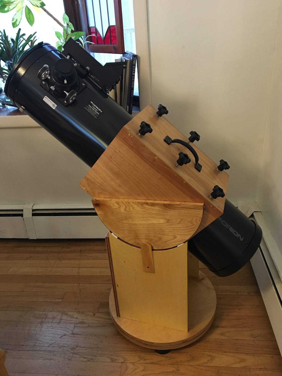
STEP 6 - THE STAND
The mount works really well, however, it sits very low for someone tall. Orion, which most of my equipment comes from, has a nice telescope stand for $140, however, as someone else pointed out, it is just four pieces of wood stuck together so I decided to make my own. I saw a homemade stand on the 10-minute astronomy website and used it as a model for my stand although I made several modifications.

To start, I cut out a 'T' in some of the leftover ¾" Furniture plywood. The size was governed by the placement of the ground board feet. The legs sit under the ground board feet. In my case the width 4½ inches, the top of the 'T' was 20 inches, and the front piece was 13 inches from where it met the the top piece.

The legs consist of leftover deck boards a little over 3 inches in width and 12 inches in length.

The legs consist of leftover deck boards a little over 3 inches in width and 12 inches in length.

I first made the back legs by attaching two pieces to form an 'L' shape with wood glue and deck screws countersunk in the wood. Then I attached them to the 'T' under where the feet will go with glue and more deck screws. I did not attach a second piece to the front leg at first, however, upon checking the stability, I attached a second piece in a 'T' shape using wood glue and deck screws.

The stand was solid, however, there was a little play when I moved the scope so I decided to do overkill and add more support. I attached a 1" x 2" to the back legs and then another 3" diameter deck board from the front leg to the middle of the 1" x 2". Again, I used wood glue and deck screws to attach the support beams to each other and to the legs.
Finally I paint the stand with with outdoor black paint.
AND FINALLY, IT"S SOLID, AND IT'S DONE!

Tool List
Hammer
Table saw
Clamps
Two cordless drills/screw drivers
Level
Router with homemade wooden arm attachment, nail is the turning pivot point


