For most, the Orion Nebula is one of the first deep sky objects that people getting into astrophotography take since it is pretty and it is easy to spot. You don't even have to take a very long exposure to get a decent looking image. My first deep sky image was a 25 second exposure of M42 taken last year (1/1/15). I was happy with the image but I also have learned a lot since taking that shot last year and so revisited the Orion Nebula from my driveway the other night. My regular astronomy meeting with the
Boothe Memorial Astronomical Society (BMAS) was cancelled because the town (Stratford) never plowed the road/parking lot to our meeting area and so, I took the following image from my driveway on 2/5/16.
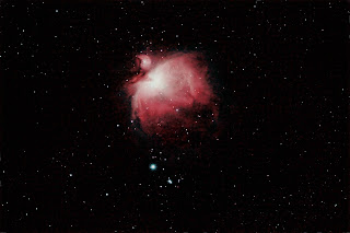
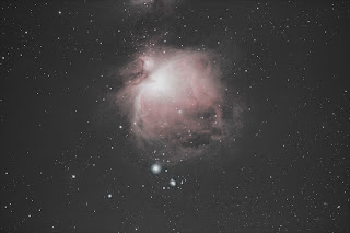
M42 - The Great Orion Nebula
Location: Monroe, CT
Date/Time: 2/5/16 9:17 pm
Camera: Canon EOS Rebel T3i, Backyard EOS
Filter: Astronomik CLS, 2" (48mm)
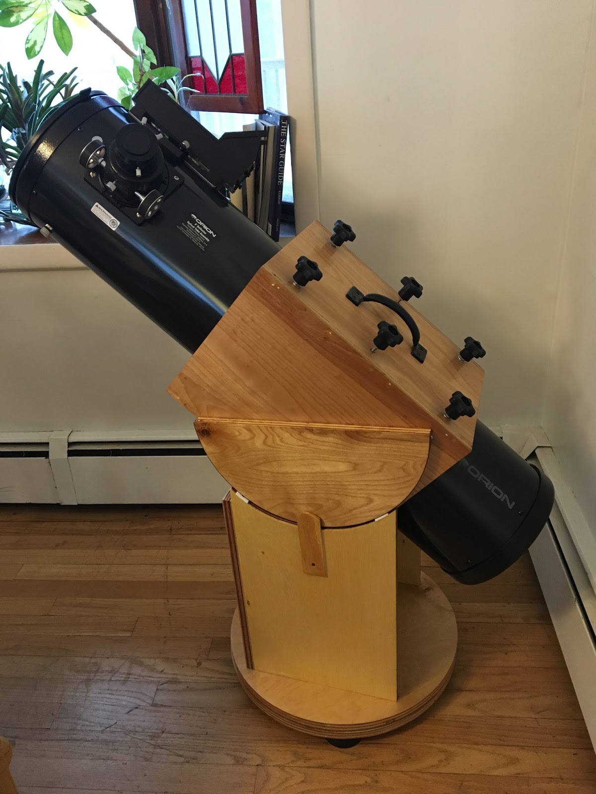
Telescope: Orion ED80 80mm f/7.5 Apochromatic Refractor Telescope
Mount: Orion Sirius EQ-G GoTo Telescope Mount
Autoguiding: QHY-5L-II-M attached to and Orion Short Tube 80mm
Focal Length: 600mm
f/7.5
Exposure: 7-300s, 10-60s, 10-10s, 1-10s (total exposure, 46min 50s)
ISO: 800
Post Processing: DSS, PS
Larer, I used Adobe Lightroom to modify colors and perform a noise reduction.
I highly recommend purchasing one the online/CD books by
Jerry Lodriguss. My wife purchased
A Guide to Astrophotography as a gift last year and it has been very helpful. In addition to step-by-step tutorials, he also gives short video tutorials on processing with Photoshop.
Quick Processing Tutorial
Introduction
This tutorial is for someone who has some knowledge and understanding of astrophotography but not at an advanced level especially since I do not consider myself advanced. Right off the bat, after I aligned the scope of course, I realized I had to wait another 30 minutes for my goto mount to do the meridian shift; however, I used that time to take test photos with and without the
Astronomik CLS pollution filter.
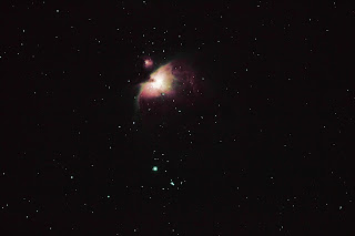
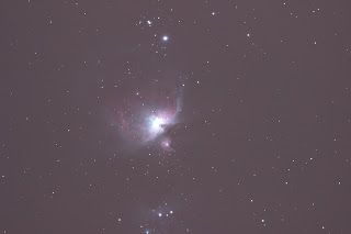 |
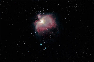
| without filter |
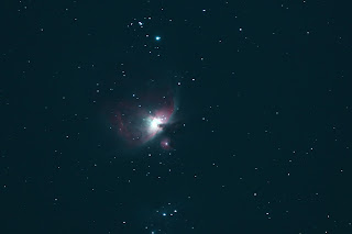 |
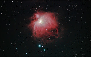
| with filter |
Both images above are two minute exposures at 800 ISO. The only difference is the first image was taken without the filter and the second was taken with a filter. Based on the results I chose to use the filter. Also, these photos appear upside when compared to the images rest of the images as the camera flipped when the mount completed the meridian shift.
Step 1 - Deciding on Length and How Many Exposures
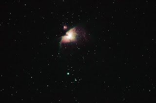
After viewing several very nice Orion images and what was feasible for my setup and time, I decided to shoot 11 - 300 second exposures, 10 - 60 second exposures, and 10 - 10 second exposures. Also, 3 - 300 second dark exposures, 3 - 60 second dark exposures, and 3 - 10 second dark exposures were taken.
Note: The reason I chose different exposure times is because the core of Orion is very bright compared to the rest. By merging the different exposures into one image in Photoshop, the brightness of the core can be reduced so the finer detail can be seen.
After reviewing the resultant sub-exposures, I deleted four of the 300 second exposures as they were streaking, most likely the wind, it was a bit breezy.
Step 2 - Stacking
I have had pretty good luck with
Deep Sky Stacker (DSS) and used it to stack each set of sub-exposures, thus I had three master exposure images: 1) master_10s, 2) master_60s, and 3) master_300s. The following images are from DSS, minor processing was done there.
 |
| 10 second |
 |
| 60 second |
 |
| 300 second |
Step 3 - Processing the Stacked Images
Now I processed each of the master exposures in Photoshop. The main thing I did was neutralize the background night glow. See
astropix.
 |
| 10 second |
 |
| 60 second |
 |
| 300 second |
Step 4 - Sizing the Images using Photoshop
The images must be the same size when merging them. This can be done easily in Photoshop by using the crop function. Choose one of the images and start the crop on a star in one corner and end the crop on another star in the opposite corner. Repeat this on the other images using the same stars to crop on. I increased the size to make make the crop more accurate.
Step 5 - Merging the Images using Photoshop (Layers & Masks)
This was the hard part and I followed instructions by
Jerry Lodriguss as well a video tutorial from
Dave Smith on Youtube.
The general procedure is:
1) to open two images to be merged, a short and long exposure.
2) select the short exposure and select all (Ctrl + A).
3) copy (Ctrl + C).
4) open the long exposure and paste (Ctrl + V).
5) select the mask button on the bottom of layers pallette.
6) (Alt + click) on the mask next to the layer 1 button.
7) click on the white mask exposure and paste (Ctrl + V).
8) open the Gaussian Filter under the filters pulled down menu.
9) use 30 pixels for the size.
10) open layer one to see the result.
I first merged the 10 second exposure with the 60 second exposure and then merged that new exposure with the 300 second exposure. Later, I took one 10 second exposure and merged it with the final image to improve the core even more.
 |
| 10 sec + 60 sec |
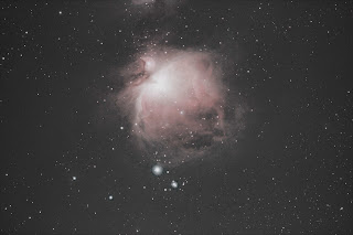
 |
| 10 sec + 60 sec + 300 sec |
You can now play with image in Photoshop, Lightroom, Picasa or any other to bring out some of the other detail.
Note: throughout this activity, I saved numerous versions. Also. the deep reddish color of my image may be due to the pollution filter. Ideally, I would go out the next night or as soon as I could and do a session without the filter to see if the color is the same. I live in a very forested part of Connecticut so it is not that easy to check this not to mention the weather. Connecticut is not exactly Arizona (my former residence for 11 years).
Other versions along the way!
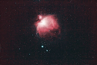
300 sec, stacked 60 sec, stacked
300 sec, stacked, 0% saturated 300 sec + 6o sec merged
300s/60s/10s merged 300s/60s/10s + 10s merged